
A common description of AutoCAD layers is that they are like “transparent sheets on which objects are drawn” (AutoCAD – What is a Layer?”). While this analogy may help beginners, it does not provide a full understanding of how to define, name amd use “LAYERS” in making intelligent comprehensive and adaptable drawings.
This article presents a database-based model that more thoroughly explains how layers can be used to make a drawing database more efficient for storage, recoverey and use of data and to make drawings more accurate and efficient in conveying information. It also covers the concepts of BYLAYER and BYBLOCK and explains why AutoCAD does not use the term BYOBJECT and how we are encouraged to think back-to-front about the concept of BYLAYER as being a default and fixed properties being an optional overide when in fact it should logically be the other way round with BYLAYER being a drawing and database efficiency option.
IF A LAYER is not a sheet, surface, or container holding OBJECTS….what is it?
Before we discuss LAYERS let’s look at OBJECTS and before we discuss OBJECTS let’s look at DATABASES.
I am assuming that since you are investigating LAYERS you are already familiar with CAD at a professional level.
The first thing I would like you to do is FORGET the common description of CAD LAYERS as “like transparent sheets on which objects are drawn”. While this analogy, evolved from manual drafting and is simple to explain and understand, it limits understanding of the real benefits and power of using layers.
Think instead of the wider figurative meaning of the term “layers”e.g. “layers” of society.
This database view is the foundation for more advanced layer management systems such as MycadHELPER’s composite-coincident-overlay modelling approach, because it treats layers as data classification and control mechanisms, not as drawing surfaces.
Let’s start with some terminology:
Drawings consist of GRAPHICAL OBJECTS represented on a computer screen or printed on paper. The source of the information is a DATABASE (file). Each object has a RECORD in the DATABASE. Each record is a list of the PROPERTIES of the object and instructions on how to represent it. The number and names of the properties vary according to the TYPE of object. The term TYPE is used in three different ways: 1. A LAYER definition, 2. PRODUCT-TYPE e.g. Brick Wall 3. GRAPHICAL-TYPE e.g. Line, Arc, Circle. In this context we are refering to product-type i.e. the definiton of a brick wall. Object properties may be a singular value (e.g. its layer-name), a switch (e.g. ON/OFF) or a selection LIST (e.g. Color Red, Yellow, Green). Each property has a NAME and a VALUE. The property-names are consistent and specific to objects of the same product-type. The property values may be assigned to an object in three ways: 1. by the the system – as the object is drawn, 2. by individual change, 3. from a LIST related to the product type. The list defines a LAYER. A group of Layers might be used to display a particular DRAWING FUNCTION e.g. Electrical plan level 02.
To understand “LAYERS” we first need to be familiar with the drawing database:
Key aspects of a drawing database:
- Drawing OBJECTS
- Object PROPERTIES
- Symbol Tables
- LAYERS
- BLOCK Definitions and References
- Layout and Paper Space Information
- Named Object Dictionaries
- Dimension and Annotation Systems
- Display and Visibility Controls
- External References (Xrefs)
- System Variables and Drawing Settings
- Relationships Between Database Elements
OBJECTS and LAYERS
At this time we don’t need to study the complete database structure BUT we do need to understand OBJECTS and LAYERS.
OBJECT types:
- Lines
- Polylines
- Arcs
- Circles
- Splines
- Ellipses
- Hatches
- Text and MText
- Dimensions
- Leaders
- Tables
- Blocks (inserted references)
- 3D solids
- Surfaces
- Meshes
- Point objects
Entries in an object record:
- A unique object ID (handle)
- A type definition
- Geometric data
- Object properties
- Relationships to other database objects
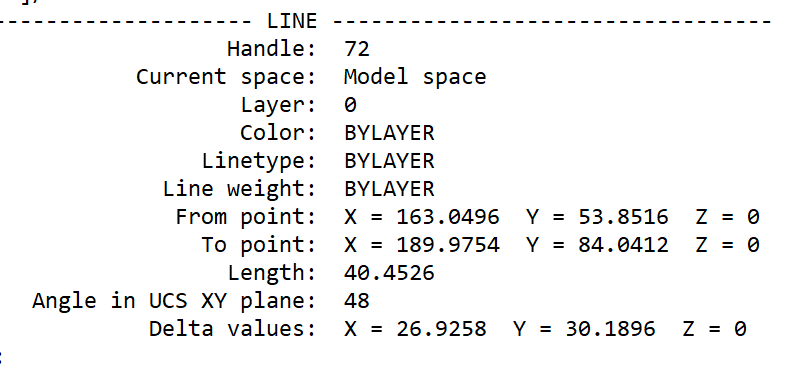
e.g. a record of a line consists of:
- Drawing space (paper or model)
- Layer name
- Start point coordinates
- End point coordinates
- Colour
- Linetype
- Line-type scale
- Lineweight
- Transparency
- Plot style information?
A typical LAYER record
| Function | Controls |
|---|---|
| Identification | Name, Description |
| Appearance | Colour, Linetype, Lineweight, Transparency, Material |
| Output | Plot Style, Plot/No Plot |
| Visibility | On/Off, Freeze/Thaw, VP Freeze |
| Editing | Lock/Unlock |
| Viewport Management | New VP Freeze |
| Organisation | Current, In Use, Xref-dependent, Filters |
What does BYLAYER really mean?
In an OBJECT PROPERTY definition (record) property values can be assigned directly to the object or by reference to a layer-property-list e.g. the property of Color can be assigned directly to the object e.g. Color = Red or BYLAYER e.g. Color = bylayer.
The layer-name is the key to an object’s definition. An object’s layer-name points to a separate named database component defining the object’s such that an object with the reference layer “Brick-Wall” might have its property of “Color” with the Value “Red” but in the object’s own definition the property named “Color” would be shown as “bylayer” meaning that when the object is drawn or regenerated the object references the layer definition and its color will be Red.
Common practice recommends that wherever practicable object property values should be assigned by reference to a LAYER definition rather than directly to the object. To do this we need to distinguish between property NAMES (e.g. Color)and property VALUES(e.g. Red).
Each value in a layer description can be assigned in one of three ways. Just to remind us; “object properties may be a singular value (e.g. its layer-name), a switch (e.g. ON/OFF) or a selection LIST (e.g. Color Red, Yellow, Green).”
Keep in mind that the term “LAYER” can refer to:
- A List – of the properties describing a particular object-function.
- The Name – of an individual object-property-list
- The Value of the property named
- A Collection – of same type of objects defined by their layername.
Values assigned by reference to a defined layer are said to be BYLAYER. There is no formal description in AutoCAD for properties directly asigned to objects but some CAD users loosely call them by-object. Those values assigned from a layer-properties-list are said to be BYLAYER and the word “BYLAYER” is the value included in the object property list . e.g. property ID color property value BYLAYER. There is of course no color “BYLAYER” so when the object is drawn on the screen or printed its color is referenced from the specified layer definition e.g. RED.
An OBJECT database record looks like this:
(show image of a record)
(add link to web page showing a summaryof a drawing database)
It is worth emphasising that there could be as many different layers (property lists) as there are objects in a drawing but objects of the same object type can reference a same single named and saved layer-properties-list. Those property values that are referenced from the list instead of being assigned ditrectly to the object.
What about MycadHELPER?
Later I will show how a layer NAME can imply other layer properties not covered by CAD layer properties lists such as construction-phase, drawing-function, view point and drawing cross-section or floor-level. This will lead to a separate discussion of layer-naming standards and coincident-overlay-drafting.
(show example of several complex layer names)
(provide a link to relevant web page)
(show an object record – highlight the item “Layer”)
(show a layer being highlighted)
The layer name is one of the most important properties in an object’s record.
We now know that a “layer” has nothing to do with anything physical such as an overlay-sheet. We also know that while layernames can be used to identify like objects, a layer is not a specific group or number of objects. The confirmation being that a layer-property-list may be un-referenced, (empty).
How do OBJECTS and LAYERS get their property NAMES and VALUES
A key item in the object record is the name of a layer properties-list assigned at the time of drawing by the current layer system-variable CLAYER. In a NEW blank drawing the initial and only layer is Layer 0 (zero). Many lists (Layers) may be required to describe the various object types in a drawing. Thses are created and recorded in the database separately from object records. Once recorded, all layer-lists remain in the database unless PURGED.
A typical NEW object record might look like this:
| General Function | Layer Property | Purpose |
|---|---|---|
| Identification | Layer Name | Unique identifier used to assign objects to the layer. |
| Description (optional) | Human-readable explanation of the layer’s purpose. | |
| Appearance | Colour | Default display and plotting colour for objects. |
| Linetype | Continuous, Hidden, Centre, Phantom, etc. | |
| Lineweight | Thickness used for display and plotting. | |
| Transparency | Controls object transparency. | |
| Material | Rendering material for 3D objects. | |
| Plot Style (STB drawings) | Controls plotted appearance when named plot styles are used. | |
| Visibility | On/Off | Shows or hides the layer. |
| Freeze/Thaw | Removes or restores the layer from drawing regeneration. | |
| VP Freeze | Freeze layer in selected viewports only. | |
| Editing Control | Lock/Unlock | Prevents modification while remaining visible. |
| Printing Control | Plot/No Plot | Determines whether objects on the layer are printed. |
| Standards & Management | Layer Filters | Organize large layer collections. |
| Layer States | Save and restore groups of layer settings. | |
| Layer Reconciliation Status | Tracks newly created layers for standards compliance. |
Looking at these by function
The properties naturally fall into six broad categories:
1. Identification
These define what the layer is.
- Layer Name
- Description
2. Default Object Appearance
These determine how new BYLAYER objects will appear.
- Colour
- Linetype
- Lineweight
- Transparency
- Material
- Plot Style
These are the properties most users think of when discussing layers because they are inherited by objects whose properties are set to BYLAYER.
3. Visibility Control
These determine whether objects are displayed.
- On/Off
- Freeze/Thaw
- Viewport Freeze
4. Editing Control
These determine whether objects can be modified.
- Lock
5. Printing Control
These determine whether objects appear on printed output.
- Plot / No Plot
6. Management Functions
These assist in organizing and controlling complex drawings.
- Layer Filters
- Layer States
- Layer Reconciliation
A useful distinction
For teaching purposes, it is worth separating layer properties into two major groups:
A. Properties inherited by objects
These become object properties when an object is created BYLAYER.
- Colour
- Linetype
- Lineweight
- Transparency
- Material
- Plot Style
B. Properties that affect the layer itself
These are not inherited by objects.
- Layer Name
- Description
- On/Off
- Freeze/Thaw
- VP Freeze
- Lock
- Plot/No Plot
- Filters
- Layer States
- Reconciliation
Some values relate to an object’s appearance and are said to be BYLAYER.
- Colour
- Linetype
- Lineweight
- Transparency
- Material
- Plot Style
Others control a layer’s visibility and edit-ability and hence management of objects for display and printing.
- Freeze/Thaw
- VP Freeze
- Lock
- Plot/No Plot
The resulting object properties are said to be BYLAYER
modification of both of these sets of properties these layer properties
others such as
- Filters
- Layer States
- Reconciliation
manage groups of layers
are assigned directly to an object record are commonly known as BYOBJECT
default
I think this classification aligns very well with your broader explanation that a layer should be understood as an object-property management system, rather than as a “transparent overlay.”
Drawing production concepts:
Workspaces – operator’s work enviroments (screen, menus etc)
Workzones – production drawing layer states – automated by MycadHELPER
C
Drawing OBJECTS are constructions such as points, circles and lines. Each object has a number of properties.
Object properties may be assigned directly to an object or read from a reference-list. Object-property reference-lists are known as LAYERS.
Two confusions occur here:
Both Objects and Layers have property lists. Some properties, such as geometric properties, are limited to object records while others are specific to layer-property-lists and yet others can refer to either one or more layers or one or more objects. Confusing?? We all know what an object is; a line or circle etc, and most of us think we know what a layer is; “a transparent sheet on which objects are drawn” but the layer concept needs a better explanation.
Let’s start with objects.
Each object record holds a number of properties including but not limited to:
- An identity handle
- Model-space or paper-space location
- A Layer-name,
- Appearance properties
- Various other properties related to specific object types
- Object geometry
The key properties of each record are its property-list-name; known as a Layer-name. The Layer-name in an object record identifies a list of object appearance properties that may appear in both an object record and a layer-property-list.
Appearance properties:
- Colour,
- Line-type
- Line-weight
- Transparency
Appearance properties are special because they may be assigned an to object record either directly per-object or by reference to a layer-property-list by-layer. If assigned by-layer to a layer-property- list (otherwise known as a layer) the object record lists the property value as BYLAYER and the value from the layer-list becomes the property value used to draw or print the object.
Properties assigned per-object overule properties assigned by-layer.
Layer-states are layer properties not object properties.
Layerstates are operational conditions of layers rather than objects. The states are like switches that determine whether objects with the relevant layer name have the conditions ON or OFF. Layerstates are managed by layer management commands not object property commands.
- Visibility display
- Frozen/thawed regeneration
- locked/unlocked editability
- plot/no-plot plotability
- VPfreeze specific viewport
Layerstates for a drawing can be named, saved and restored.
A typical NEW object record of a simple object might look like this:
Note the that the object’s Layer in a new drawing is 0 and apearance properties are BYLAYER
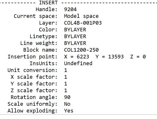
A more complex object record may look like this:
Note the specific layer-name and the additional properties relating to a BLOCK.
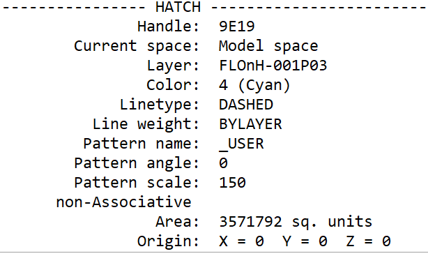
Or this:
Note the mixture of properties by-object and by-layer
,,,,,,,,,,,,,,,,,,,,,,,,,,,,,,,,,,,,,,,,,,,,,,,,,,,,,,,,,,,,,,,,,,,,,,,,,,,,,,,,,,,,,,,,,,,,,,,,,,,,,,,,,,,,,,,,,,,,,,,,,
There may be as many different layernames (LAYERS) as there are different objects in the drawing. Each list has its own name (layer-name).
In addition to object geometry………………….
A typical name might be “WALLS”. Different object property lists may be used in a drawing to differentiate between different drawing object types such that “WALLS” display differently to “FLOORS”. These lists are (somewhat misleadingly) generically called “LAYERS”. We know why but we know that a property-list has nothing to do with anything physical such as an overlay sheet of anything. But for convenience we refer to the referance of visual properties to a separate list, rather than being part of the object record, as “BYLAYER”.
Although visual properties of new objects are by default drawn from a separate list they may alternatively be fixed in the record of the object. This is known as “by-object” or more commonly “BYOBJECT”, (AutoCAD does not use this term) and thus become a permanent property of the object.
The key item in the object record is the name of the visual properties-list (otherwise known as LAYER) assigned at the time of drawing by the current layer system variable CLAYER. In a NEW blank drawing the initial and only layer is layer 0 (zero). As many lists as required to describe various object types in a drawing may be created and recordd in the database separately from object records. Once recorded, all lists remain in the database unless PURGED.
Benefits of using lists:
- Many objects may reference the same list rather than applying individual properties to each object significantly reducing the size of the database
- Provide a quick way of definng new objects
- Provide a way of identifying objects of the same property specification.
Now let’s look at LAYERS
Initially all object properties including a property list name are aquired from the system variable “CLAYER” as set by the OPTIONS command.
As work proceeds other property lists may be created and those property lists may be applied to new objects by resetting system-varable CLAYER to the new name. Alternatively existing objects may have their properties changed to those of a different list or may have individual properties assigned directly to the object thus overiding those of the list active when the object was drawn. Most object properties refer to lists other than the default list 0 because list 0 (“Layer 0”) has other special functions.
The list name current when an object is drawn (CLAYER) is retained as a fixed property of the object. BUT list properties of colour, linetype and line-weight can be redfined as fixed properties of the object thus allowing objects to have properties redefined by-list or by-object (later we wil also talk about by-block) without losing the basic identity or type of the object. In common practice most object properties are set by-list, thus becoming dependent on the particular list that the properties reference. These options are said to be BYLAYER and BYOBJECT and BYBLOCK. (AutoCAD does not use the term “BYOBJECT”)
Each list has a unique name that a special permanent property of the list. (AutoCAD calls property lists LAYERS but let’s use “LAYERNAME” instead of “layer-name” or “property-list” to emphasise that the name of the list is permanently assigned to the object record regardless of how the the object’s properties are assigned, whether BYLAYER or BYOBJECT. It is this CLAYER name that may be used to identify objects with the same visual properties.
Here is what a typical LAYER record looks like:

Note that the Layer Name is a property of the “LAYER” but “LAYER” and its name are two different concepts; one being a property list and the other an object propertyand both are changeable properties of actual OBJECTS. Sounds confusing but the distiction is important to the use of LAYERS.
Here are the key points to remember:
- A LAYER is a pre-defined and named LIST of OBJECT visual properties.
- Each LAYER has a unique name (such as “WALLS”).
- An object’s layer name is normally fixed to the object (BYOBJECT).
Each OBJECT has three groups of properties normally initially assigned by the system variable CLAYER
- A Layername
- Several Visual – color, line-type, transparency etc
- Operational – plot-style. no-plot-style
A 4th group of Geometric properties: line, arc, point, coordinates UCS etc are assigned to the object, (independent of the layerb name), by the drawing process.
OBJECT Properties may be asssigned
- BYLAYER — inherited from the cuurent CLAYER system-variable list definitions.
- BYBLOCK — applied by a CHPROP command.
- By-Object — applied by a CHPROP command. (AutoCAD does not use the term BYOBJECT).
- Geometric – created as the object is drawn. (AutoCAD does not use the term GEOMETRIC)
Comments:
Renaming a layer effectively creates a NEW object visual property list with a new name albeit with the same properties as the former.
LAYER definitions remain in the system whether or not there are any objects that reference them.
Conversion of one object’s properties from BYLAYER to BYBLOCK or BYOBJECT does not change the LAYER’S application to other objects with the same LAYERNAME.
Unreferenced layers may be purged.
BYLAYER allows the properties of all objects with the same LAYERNAME to be controlled by redefining the properties in the list.
BYOBJECT allows properties to be changed making the relevant properties permanent for the object
For example, if LAYER “WALLS” has its BYLAYER colour property definition changed from say GREEN to RED all objects with the LAYERNAME “WALLS” and colour property BYLAYER will change from GREEN to RED. On the other hand if an OBJECT’S colour property is either already BYOBJECT or changed to BYOBJECT the colour property, if changed from GREEN to RED would change those particular objects but not any remaining objects with the same LAYERNAME. Theywill retain their original BYLAYER colour.
In other words; objects with the same layer-name property can have different same-property settings — e.g. the colors of some objects can be BYLAYER and others BYOBJECT or BYBLOCK.
It is not difficult to see the potential for confusion arising from the BYLAYER/BYOBJECT/BYBLOCK conflict; hence most operators use properties BYLAYER except for specific purposes in some OBJECTS or BLOCKS. Refer also to the use of LAYER 0 objects in BLOCKS.
CHPROP lets you change:
- Color
- Layer
- Linetype
- Linetype Scale
- Lineweight
- Thickness
- Transparency
- Material
- Annotative setting
- Plot Style (when named plot styles are used)
Other useful commands:
- MATCHPROP — copy properties between objects
- LAYMATCH — match objects from another layer
- LMAN — manage layer states
Opinion. Some tutors recomend creation of a template drawing with pre-named and pre-defined layers before any objects are created thus avoiding the delay of having to repeatedly create new LAYERNAMES and define new property lists. A counter effect is that the drawing database may become overloaded with irelevant lists of properties that must then later be PURGED. It is better to have a manageble layer naming standard that can easily and more conveniently managed on-the-run rather than searching lists to find an appropriate name with appropriate properties.
QUESTION.
What do you think is the best short description of a Layer?
- A transparent overlay film on which one draws objects that have the same named list of properties.
- A named list of object properties that may be assigned to objects with the same properties in spite of their location in space.