
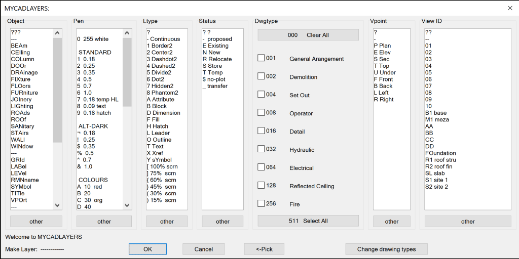
MycadLAYERS provides a LAYERNAMING and MANAGEMENT dialog box that displays each layer field as scroll-able lists of optional user choices. plus an option for user generated alternatives. An operator may type a response into an “other” box if the options provided are unsuitable. The dialog box can save time by using the current layer name as a template in which fields may be optionally changed to create the desired new layername. The resulting layername can then become the current layer. New layers are automatically created with the correct color and line-type.
Examples illustrated are Architectural but are fully customizable.
Layer names are made up of seven fields: Object, Pen, Line-type, Status, Drawing-type, Viewpoint and View ID. All but the Drawing-type are scrollable columns that can contain as many options as desired. All options are editable to suit the individual projects and disciplines. Drawing-type has nine check-boxes related to the bit-codes 001 to 256. All or as many of these as is relevant may be checked indicating what drawing-types a particular layer appears in. The drawing-types themselves are also editable using a separate dialogue box “Change drawing types” that allows the creation of alternative drawing-type schemes.
If an acceptable code is not found in any column the user may create a new code using the “other” option at the bottom of the column.
The “Make Layer” note at the bottom-left by default shows the current layer. This changes progressively as options are selected to indicate the new layer name. Typically only one or two fields may need to be changed thus further reducing the effort to create new layers. When finished press “OK” and the new layer complete with correct color and line-type will be created and made current.
The drawing-type names to the right of the check-boxes show capitalized letters that may be used as mnemonic substitutes for entering the full three digit number when using keyboard entry instead of the dialogue box.
Keyboard vs dialog-box
The dialogue-box is designed mainly for new users. Experienced users will find it quicker to use the keyboard once they are familiar with MycadLAYERS naming conventions. The keyboard is as always a faster and more complete interface and prompts the user through each relevant data field, accepting only appropriate entries. All MycadLAYERS commands that use Layer names accept the keyboard method.
Drawing-types relevant to project
Although for many projects the preferred drawing types and code assignments will be the same, on occasions it may be necessary to use a different drawing-type scheme. This is provided for in the system. It is possible to have a different set of drawing types for every project. The selected Drawing Types Set is saved with the drawing and automatically appears in the layer dialog box in subsequent CAD sessions. To change the scheme select “Change drawing types” in the bottom-right corner of the Layer dialogue-box.

Examples of OBJECT codes might be:
Construction: — all ALUminium BEAm BLOckwork BRIckwork CABinetwork CEIling CERamic tiles COLumn CONcrete DOOr DP_ DownPipe EARthwork EQUipment FENce FINish FiXIngs (screw) FLAshing FIXture (basin) FLOor (surface) FOOting FURniture GLAzing GRAphic/sign GRIlle HANdrail HARdware INSulation JOInery KERb MEMbrane METalwork PAInt PARtition PAVing PIPe PLAster RENder RESilient fin ROAd ROOf SEAlant SLAb STAirs STEel STUd walls TILes THReshold TRUss VENt WALl WINdow WIRe WOOd
Discipline: BUIder CIVil COMunictns ELElectrical ESCalator EXTernal GRAphics HYDraulics INTerior LANdscape LIFt MEChanical STRuctural SURveyor
Reference: FRAme GRId LABel LEVel LEGend SCHedule TITle VPOrt
Examples of PEN codes might be:
Pens printed in BLACK – standard line thickness:
In order of Pen-number, Line-thickness, Full Color Dark Color Light Color
1 0.18 red A clr 12 G clr 14
2 0.25 yellow B clr 52 H clr 54
3 0.35 green C clr 92 I clr 94
4 0.5 cyan D 1clr 32 J 134
5 0.7 blue E clr 172 K clr 174
6 1.0 magenta F clr 212 L clr 214
7 0.18 white temporary highlight.
8 0.18 light grey hatch
9 0.18 dark grey grids
Pens printed in COLOR – line thickness custom
In order of Pen-number, Color-number, Plot color
Colors:
M 10 red, N 30 org, O 50 yel, P 70 lime, Q 90 grn, R 110 aqua, S 130 cyan, T 150 lt-blu, U 170 blu, W 210 mag, V 190 prpl , W 210 mag, X 230 crim, Y 35 brown, Z 11 peach
Greys:
! clr 250 15%, $ clr 251 30%, % clr 252 45%, ^ clr 253 60%, & clr 254 75%
Examples of LINETYPE might be:
– continuous 1 border 2 center 3 dashdot 4 dashed 5 divide 6 dot 7 hidden 8 phantom Special A Attrib B Block D Dimension F Fill H Hatch L Leader T Text M mview Xref Y sYmbol S Sewe
Examples of STATUS or STAGE might be:
Status: – proposed B asBuilt D Demolish E Existing F Future M Msured N New O Obsolete P Prelim R Relocate S Set-out T Temp U re-Used
Stage: – current 1 2 3 4 5 6 7 8 9 0